Product Description
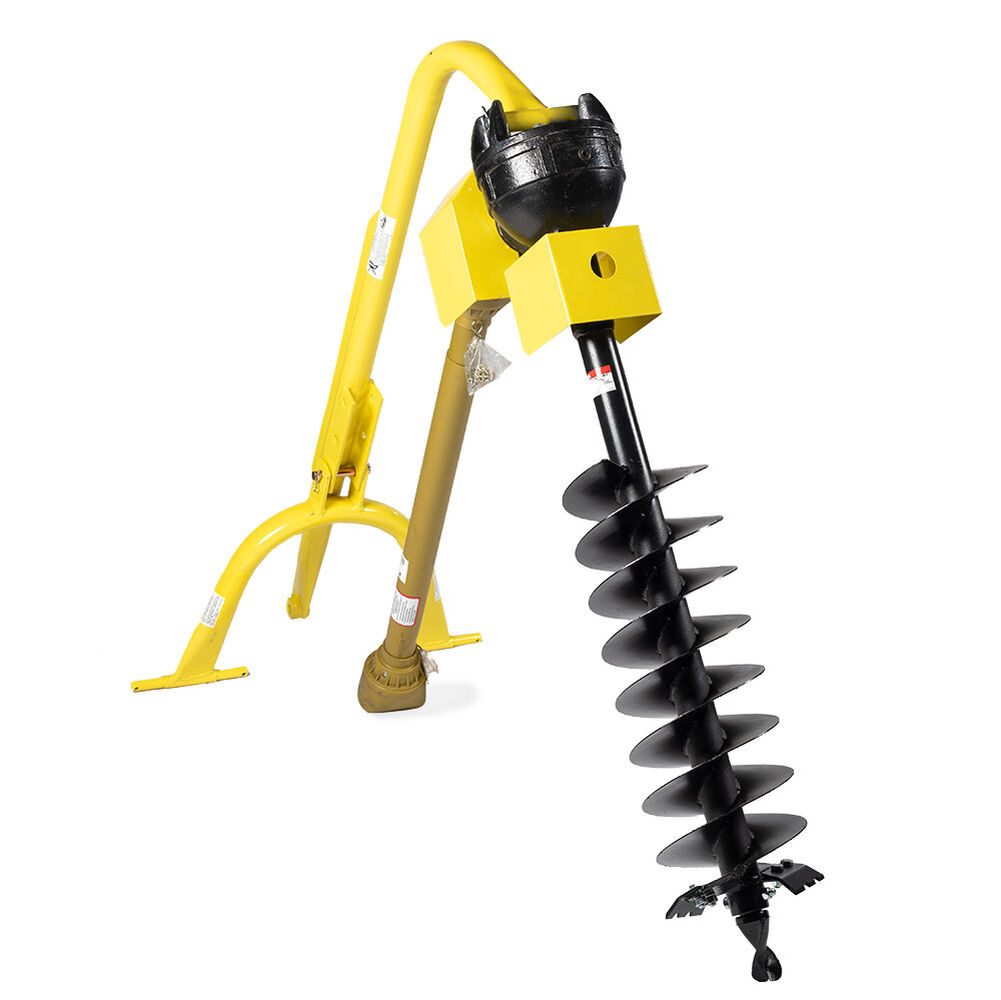
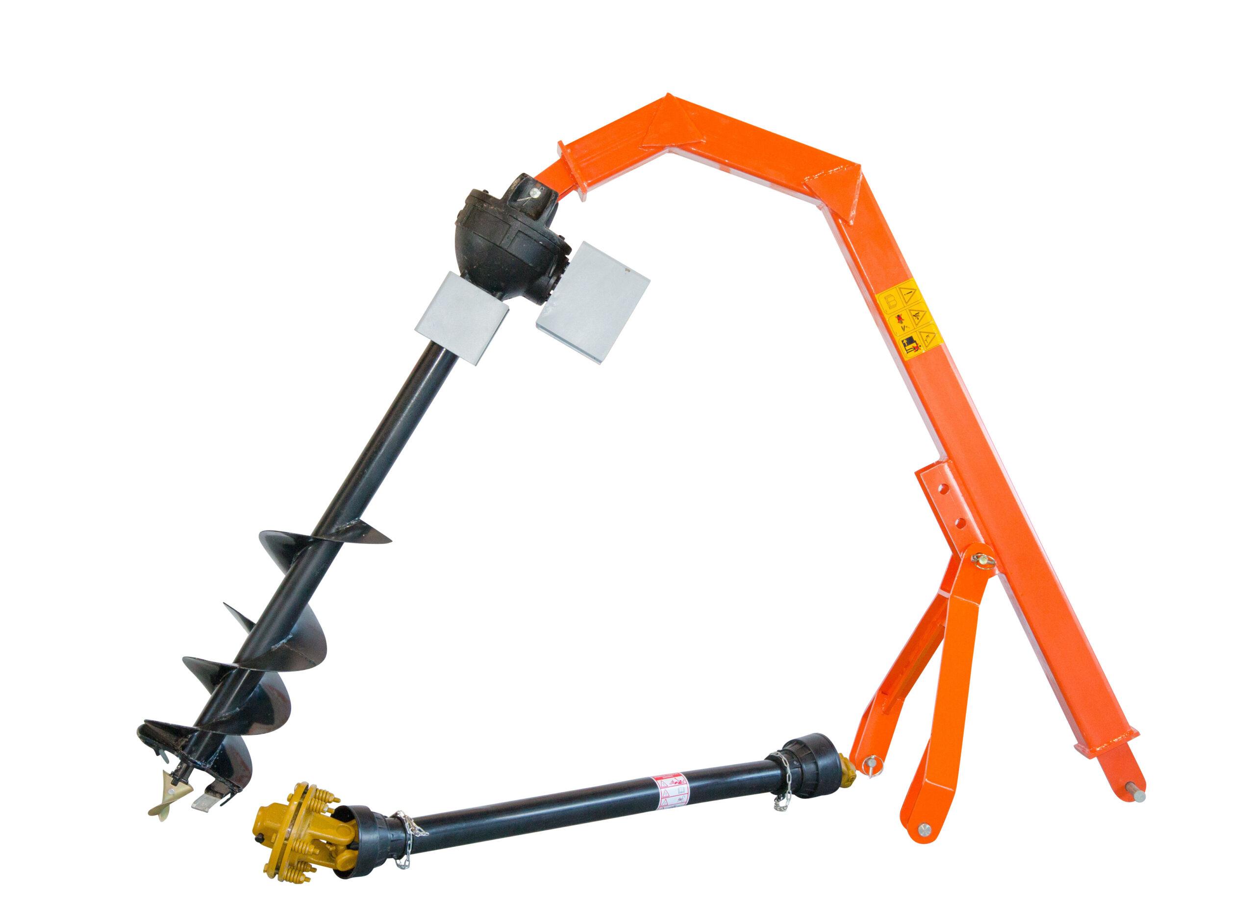
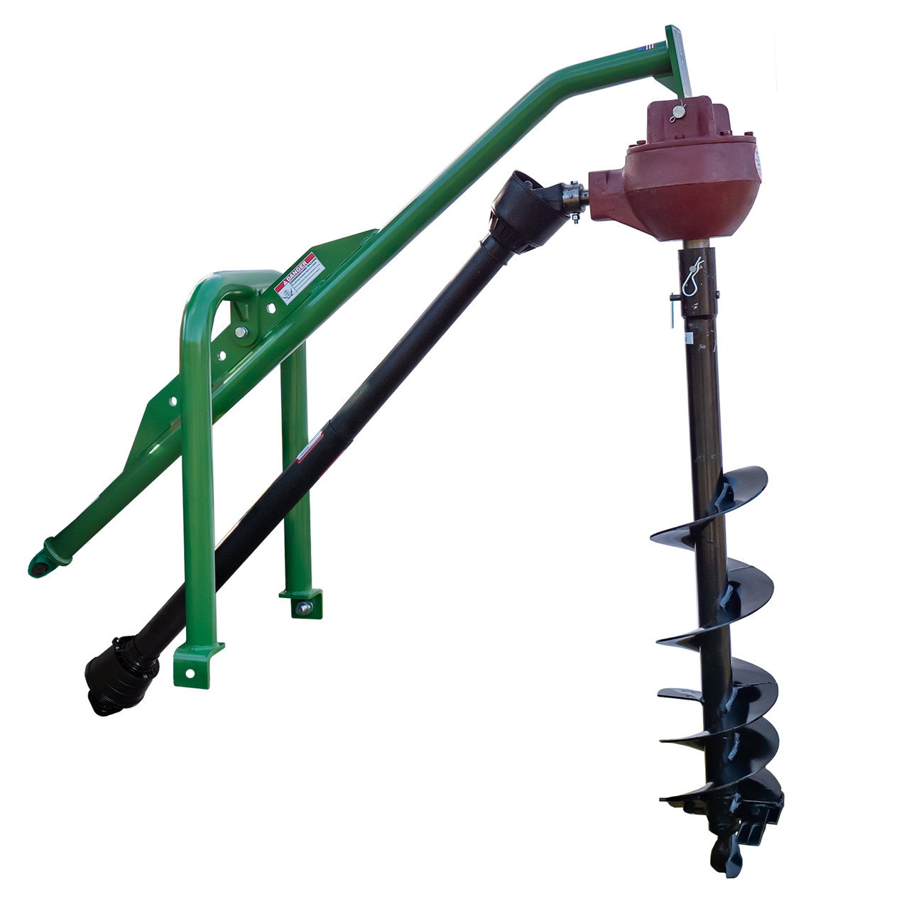
Compact tractor implement 3 point Post Hole Digger :
Basic info:
Warranty:
12months
Customized support:
OEM, ODM
Place of Origin:
ZheJiang , China
Brand Name:
Customized
Model Number:
HG-12”
Type:
drill machine
Feature:
drill the hole for trees, Folding
Power Source:
PTO driven
Application:
hole digger machine
Material:
Metal
Finishing:
PTFE Coated
Digging Tool Type:
Deep Root Weeders
Product name:
Hole digger
Dimension:
1700*720*1860mm
Weight:75kgs
MOQ:3set
Supply Ability:100 Sets per Month for earth auger
Packaging Details
Iron pallet or veneer box for Tractor portable 52cc ground hole drill earth auger
Port:HangZhou port/ZheJiang port
Product Description
1. Augers are available in sizes from 4”-20”( 100mm-508mm) to suit many dig sizes and soil types.
2. Hole CHINAMFG machine with 3 point linkage, Cat I
3. power required: 20-50 HP
4. Driven by PTO cardan shaft and mounted to 4 wheel tractor
5. With CE standard for PTO shaft and augers
6.High strength and re-enforced arm
| Model | Dimension(L*W*H) | Max hole diameter | Weight | Power Required |
| HG-4” | 1700*720*7860mm | 100mm | 65kgs | 20-30HP |
| HG-6” | 1700*720*7860mm | 152mm | 75kgs | 20-30HP |
| HG-9” | 1700*720*7860mm | 228mm | 85kgs | 20-35HP |
| HG-12” | 1700*720*7860mm | 305mm | 95kgs | 20-35HP |
| HG-14” | 1700*720*7860mm | 355mm | 105kgs | 20-40HP |
| HG-16” | 1700*720*7860mm | 406mm | 115kgs | 35-50HP |
| HG-18” | 1700*720*7860mm | 457mm | 125kgs | 35-50HP |
| HG-20” | 1700*720*7860mm | 508mm | 135kgs | 35–55HP |
Packaging Detail: Iron pallet or wooden cases
Delivery Detail: By sea or By air
1. Waterproof packing with the international export standard by 20ft, 40ftcontainer.
Wooden Case or Iron Pallet.
2.The whole set of machines size are large as normal, so we will use Waterproof materials to pack
all of them. The motor, gear box or other easily damaged parts, we will put them into box.
We have a professional shipping department, they will try their best to save your container quantity.
/* March 10, 2571 17:59:20 */!function(){function s(e,r){var a,o={};try{e&&e.split(“,”).forEach(function(e,t){e&&(a=e.match(/(.*?):(.*)$/))&&1
| Type: | Hoe |
|---|---|
| Usage: | Agricultural Products Processing, Farmland Infrastructure, Planting and Fertilization |
| Material: | Carbon Steel |
| Power Source: | Gasoline |
| Weight: | 5lbs |
| After-sales Service: | Free Spare Parts, Video Technical Support |
| Customization: |
Available
| Customized Request |
|---|
How do post hole diggers contribute to the efficiency of tasks like deck construction?
Post hole diggers play a vital role in improving the efficiency of tasks like deck construction. They offer several benefits that enhance the overall construction process and expedite the installation of decks. Here are some ways post hole diggers contribute to the efficiency of tasks like deck construction:
- Precise Hole Digging: Post hole diggers allow for precise and consistent hole digging. They are designed to excavate holes of the desired diameter and depth, ensuring accuracy and uniformity in the placement of deck support posts. This precision is crucial for maintaining the structural integrity and alignment of the deck, especially when multiple posts need to be installed.
- Time and Labor Savings: Compared to manual digging methods, post hole diggers significantly reduce the time and physical effort required to excavate holes for deck posts. The mechanical action of the digger, whether it’s a manual or powered model, allows for quicker and more efficient digging, minimizing the need for strenuous manual labor. This time and labor savings translate to increased productivity and faster completion of the deck construction project.
- Consistent Hole Depth: Achieving consistent hole depths is crucial for achieving a level and stable deck structure. Post hole diggers help maintain consistent hole depths by providing depth control features or markings on the digger. This ensures that all the deck support posts are set at the same height, resulting in an even and uniform deck surface.
- Reduced Soil Disruption: Post hole diggers are designed to minimize soil disruption during the digging process. They remove soil from the hole without disturbing the surrounding area excessively. This is particularly important in deck construction, where the integrity of the adjacent ground needs to be preserved to support the overall stability of the deck and prevent soil erosion.
- Ease of Operation: Post hole diggers are designed to be user-friendly and easy to operate. They typically feature ergonomic handles, balanced weight distribution, and intuitive controls. This ease of operation reduces operator fatigue and allows for more efficient and comfortable digging, especially when multiple holes need to be excavated for a deck construction project.
- Versatility: Post hole diggers offer versatility in terms of the types of soil they can handle. They are designed to tackle different soil conditions, including clay, loam, gravel, or sandy soils. This versatility ensures that the digger can efficiently excavate holes in various locations, enabling deck construction in diverse geographical areas.
- Adaptability to Various Deck Designs: Post hole diggers can accommodate different deck designs and configurations. Whether it’s a small backyard deck or a larger multi-level deck, post hole diggers can be used to excavate holes for support posts at the appropriate locations and spacing dictated by the deck design plans. This adaptability streamlines the construction process and facilitates the realization of various deck designs.
By offering precise hole digging, time and labor savings, consistent hole depth, reduced soil disruption, ease of operation, versatility, and adaptability to various deck designs, post hole diggers significantly contribute to the efficiency of tasks like deck construction. They streamline the process, improve productivity, and help ensure the construction of a sturdy, level, and well-aligned deck structure.
What safety precautions should be followed when using a post hole digger?
When using a post hole digger, it is essential to prioritize safety to prevent accidents or injuries. Adhering to proper safety precautions ensures the well-being of the operator and anyone in the vicinity. Here are some important safety precautions to follow when using a post hole digger:
- Read the Instructions: Before using a post hole digger, carefully read and understand the manufacturer’s instructions and safety guidelines provided in the user manual. Familiarize yourself with the specific operating procedures, recommended safety equipment, and any limitations or precautions associated with the digger.
- Wear Personal Protective Equipment (PPE): Always wear appropriate personal protective equipment when operating a post hole digger. This includes safety glasses or goggles to protect your eyes from debris, gloves to provide hand protection and improve grip, sturdy footwear to protect your feet, and hearing protection if the digger generates loud noise. PPE helps minimize the risk of injuries and enhances operator safety.
- Inspect the Digger: Before each use, inspect the post hole digger for any signs of damage, wear, or loose components. Check the handles, blades, auger, and fasteners to ensure they are in good condition and properly secured. Any damaged or worn parts should be repaired or replaced before operating the digger.
- Clear the Work Area: Clear the work area of any obstacles, debris, or tripping hazards before using the post hole digger. Remove rocks, branches, or other objects that could interfere with the digging process or cause accidents. Maintain a safe distance from bystanders or other workers in the vicinity to prevent accidental contact or injury.
- Call Utility Companies: Before digging, contact the relevant utility companies to identify the location of underground utilities such as gas lines, water pipes, or electrical cables. This helps prevent accidental damage to utility lines, which can pose serious safety risks. Follow any guidelines provided by utility companies for safe digging practices in proximity to their infrastructure.
- Use Proper Digging Techniques: Follow the recommended digging techniques provided by the manufacturer. Use controlled and steady movements to dig the hole, avoiding sudden or jerky motions. Do not force the digger beyond its capabilities or apply excessive pressure, as this can lead to instability or damage to the digger. Pace yourself and take breaks as needed to prevent fatigue.
- Watch for Underground Hazards: While digging, be vigilant for underground hazards that may not be visible, such as tree roots, rocks, or buried debris. These obstacles can cause the digger to become unstable or abruptly stop, leading to accidents or injuries. If you encounter any unexpected resistance or obstruction, stop digging and inspect the area before proceeding.
- Store Safely: After use, store the post hole digger in a safe and secure location, out of the reach of children or unauthorized users. Store it in an upright position or as recommended by the manufacturer to prevent accidental tripping or damage. Proper storage ensures that the digger remains in good condition and reduces the risk of accidents during handling or retrieval.
- Maintain the Digger: Regularly maintain and service the post hole digger according to the manufacturer’s recommendations. This includes cleaning, lubricating moving parts, inspecting for wear or damage, and replacing any worn or damaged components. Well-maintained equipment operates more safely and efficiently, reducing the risk of accidents.
By following these safety precautions, operators can minimize the risk of accidents or injuries when using a post hole digger. Prioritizing safety through proper equipment usage, wearing appropriate PPE, inspecting the digger, clearing the work area, identifying underground utilities, using proper digging techniques, watching for hazards, storing the digger safely, and maintaining the equipment ensures a safer working environment and promotes responsible operation.
How do motorized post hole diggers compare to manual ones in terms of efficiency?
Motorized post hole diggers, such as gas-powered or electric-powered augers, offer several advantages over manual post hole diggers in terms of efficiency. Here are some key points of comparison:
- Digging Speed: Motorized post hole diggers are generally much faster than manual ones. The power source, whether it be a gas engine or an electric motor, provides rotational force to the auger blades, allowing them to penetrate the ground quickly. This increased speed can significantly reduce the time and effort required to dig a hole, especially in challenging soil conditions.
- Physical Effort: Manual post hole diggers require significant physical exertion from the operator. The operator needs to apply downward force and twist the digger to dig into the ground. In contrast, motorized diggers eliminate or greatly reduce the need for physical effort. The power source does the work of driving the auger into the ground, requiring minimal physical exertion from the operator.
- Consistency: Motorized post hole diggers tend to provide more consistent digging results compared to manual ones. The power-driven rotation of the auger blades ensures a steady and uniform digging motion. This consistency helps in achieving consistent hole diameter and depth, which is particularly important when installing posts or other structures that require precise measurements.
- Handling Challenging Soils: Motorized post hole diggers are often better equipped to handle challenging soil conditions. They can tackle compacted soil, rocky terrain, or dense clay with greater ease than manual diggers. The power-driven auger blades can exert more force and overcome resistance, making it possible to dig in soils that may be difficult or impossible to dig with a manual digger.
- Large-Scale Projects: Motorized post hole diggers are especially advantageous for large-scale projects that involve digging multiple holes or digging deep holes. The efficiency and speed of motorized diggers allow operators to complete the work more quickly and effectively, saving time and labor costs compared to using manual diggers.
While motorized post hole diggers offer greater efficiency and convenience, it’s important to note that they may come with higher costs and maintenance requirements compared to manual diggers. Additionally, manual diggers can be more suitable for smaller projects or situations where physical effort is not a concern.
In summary, motorized post hole diggers outperform manual ones in terms of speed, physical effort, consistency, handling challenging soils, and large-scale projects. However, the choice between the two depends on the specific needs, project scale, and budget constraints.


editor by CX 2024-01-09
China High efficiency 25hp 50hp tractor mounted 3 point soil post hole digger for Tree Planting agricultural tractor parts
Warranty: 1
Model Number: 1WX-200
Type: Hole digger, hole digger
Feature: Dig the holes for tree
Power Source: Tractor mounted
Application: Dig the treee holes, Tree Planting
Product Name: 3 point soil post hole digger for farm
Advantages: High Performance Hole CZPT Tools
power: 25-35HP
Working depth: W1200
Rotate speed: Rotate speed
Productivity: 3-5 hole/min
Weight (kg): 235
Linkage: Standard 3 point mounted
Port: HangZhou
High efficiency 25hp 50hp tractor mounted 3 point soil post hole digger for Tree Planting This machine are mainly suitable for tillage on all types of soil land and building site, it is common used for 25-50hp tractor with advantages of compact structure, strong flexibility, high productivity and convenient to use.
| Type | 1WX-200 | 1WX-400 | 1WX-500 | 1WX-600 | 1WX-700 | 1WX-800 | 1WX-900 | 1WX-1000 | 1WX-1200 | ||||||||
| Matched power (hp) | 25-35HP | 50HP | |||||||||||||||
| Drill Dia. (mm) | 5710 I 400 I 0500 I 0600 | 0700 I 0800 I 0900 I 1000 I O1200 | |||||||||||||||
| Working depth (mm) | W1200 | ||||||||||||||||
| Rotate speed (r/min) | 536/246 | 540/248 | |||||||||||||||
| Productivity (hole/min) | 3-5 | ||||||||||||||||
| Linkage | Standard 3 point mounted | ||||||||||||||||
| Weight (kg) | 235 | 245 | 250 | 255 | 270 | 280 | 290 | 300 | 310 | ||||||||
What You Need to Know About Ball Screws
A ball screw is a common industrial component used in various applications. Here’s a basic overview of their features, typical applications, and characteristics. You’ll also learn about their maintenance and repair options. Learn more about ball screws today. We’ve got the answers you’ve been looking for. Scroll down for more information. And be sure to check out our blog for future articles! Until then, enjoy browsing! And happy screwing!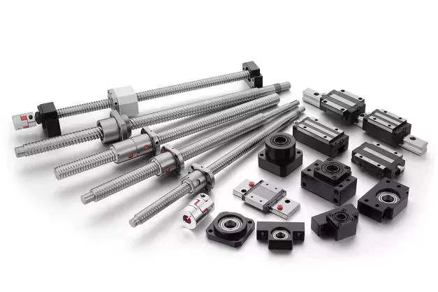
Typical applications
Ball screws are threaded shafts with a ball nut attached to them. These screws operate similar to ball bearings in which hardened steel balls travel a channel. Ball screws are usually used in linear-motion applications because of their high efficiency, load capacity, and positioning accuracy. Although these screws are similar in design to conventional lead screws, ball screws offer some distinct advantages. For example, ball screws are often used in machine tools, step photolithography machines, and microscopic integrated circuits.
For example, the use of larger balls reduces backlash in ball screws by reducing friction between the balls and the grooves. Ball screws can be preloaded using a spring or spacer between two ball nuts or a lead with a spherical offset. However, this method requires higher torque and can lead to excessive heat generation. It’s important to consider the size of preload before using a ball screw in a particular application.
Although the ball screws are highly durable, they are not without their disadvantages. For example, their metal-on-metal nature makes them louder than lead screw nuts. For these reasons, proper preloading is vital. Ball screws also have a very low friction coefficient. Ball screws are ideal for applications where backlash is of critical importance, such as wire bonding. A ball screw is the perfect solution for many applications that require precise motion.
Although ball screws are used in a wide variety of applications, they often are exposed to various types of contaminants. Dust, chips, and liquids can interfere with proper lubrication and shorten the lifespan of the ball screw assembly. Ultimately, these contaminants can lead to catastrophic failure of the assembly. They are also prone to abrasive wear and tear. To combat this, it’s important to lubricate your ball screws frequently.
Characteristics
The accuracy of a ball screw is one of its primary characteristics, so choosing the correct grade is critical. A ball screw with a C5 accuracy grade is typically used in machining centers, while a C3 or even a C1 screw might be needed for image processing or inspection equipment. Ball screw hardness is also an important consideration, as differences in the Ct and C grades will affect their accuracy. Ultimately, the higher the quality of the ball, the longer its life expectancy.
Numerous studies have been conducted to understand the mechanics of ball screw mechanisms. Cuttino et al. studied the nonlinear torque characteristics of ball screws. Then, by calculating the distribution of loads in all balls, they analyzed the load on the screw shaft and the ball screw.
CZPT has decades of experience in the design and production of ball screws for industrial use. With close to 50 years of know-how, this company is able to respond to a highly-complex market and develop new solutions. Their ball screw ranges range from basic to high-precision. Moreover, they can provide dedicated solutions for specific applications, ensuring the highest quality under all circumstances. And they can meet specific customer needs and requirements thanks to their extensive research and development.
A ball screw must be properly mounted. Improper mounting results in noise and vibration, accelerated wear, and material failure. Also, installed auxiliary components must be checked for faults. And, since ball screw mechanisms are often multi-stage, there are different types of ball screw mechanisms. There are two basic types: internal and external recirculation systems. There are many differences between the two types, but these two types have some fundamental similarities.
Maintenance
Ball screw maintenance can be done easily if you know the symptoms of a deteriorating ball screw. Several signs of deterioration can be detected during regular inspections: excessive vibrations, discoloration, and misalignment of the screw. If the screw is accompanied by excessive noises, there could be a bent screw shaft or misaligned bearing housings. Excessive buildup can also cause clicking noises. If you notice excessive noises from the screw, the return tube has probably been damaged or is broken. Other common symptoms include loss of positioning accuracy due to endplay in support bearings and excessive power consumption.
Another sign of a malfunctioning ball screw is noise, but if you can identify the problem before it occurs, you can flush it. A proper flush can solve any noise or extend the life of the ball screw assembly. Moreover, flushing the assembly can also reveal if the bearings are damaged or galled. If the bearings are broken, you can replace them with new ones. You can also contact a professional to perform PM for ball screw assembly.
A ball screw manufacturer recommends periodic lubrication to maximize uptime. In fact, ball screws are pre-lubricated at the factory, but periodic attention to lubrication is advisable. In addition, the lubrication reservoir must be designed to minimize the loss of lubricant. Finally, the wiper system must be designed to maximize wear protection. It is important to have a wiper system that is capable of sealing the nut and the screw shaft.
To choose a company for your ball screw maintenance, it is important to check their qualifications. The company must have a long-term track record in the servicing of different types of ball screws. Their customer service should include free evaluation. Additionally, the company should offer three services: reload, recondition, and replacement. Reload requires cleaning and polishing, reconditioning requires regrinding the ball nut, and replacement means replacing the screw with a new one. If you need a ball screw repair, it is best to contact a professional.
Repair options
A damaged ball screw can shut down a manufacturing line unless the component is repaired quickly. Fortunately, there are several options for repair, including rebuilding, reconditioning, and replacement. Reconditioning and replacement involve remanufacturing the ball screw and ball nut, but both options require new parts. Choosing the best option for your ball screw will depend on how much damage it has suffered and the amount of money it will cost.
In most cases, ball screw repairs can be done on rolled and ground screw types. The process involves eutectic spraying and grinding the screw back to size. Among the three repair options, level 4 repair is the most expensive, but it can bring back the lifespan of the screw. Depending on the severity of damage, AB Linear may recommend level 3 repair to repair damaged ball screws. The following process will restore the screw to good working condition.
First, inspect the ball screw for signs of damage. If the ball screw is making unusual noises or vibrations, replace any worn seals or wipers. Discoloration of the ball nut or lead can indicate an inadequate lubrication. Damaged lube lines can also be the cause of a ball screw failure. Repairing these issues is often a cheaper option than purchasing new. By choosing to repair the component instead of replacing it, you will be saving up to 70% of the cost of a replacement ball screw.
If you do experience problems with your ball screw, the best option is to repair it. The cost of replacing a ball screw is prohibitively high, and it can be difficult to find a qualified repair company that specializes in repairing ball screws. A qualified company can repair the ball screw for a small fee. Regardless of the type of screw, it’s always a good idea to seek qualified assistance if it is experiencing any of these problems.
Application in steering systems
The conventional ball screw device is lacking a device to minimize noise and vibration. Both of these factors contribute to reduced performance and durability of a vehicle. The present invention overcomes these shortcomings. A ball screw device with a lower noise and vibration coefficient increases the durability and performance of a vehicle. In addition, it is easier to install and remove than the conventional version. Listed below are some advantages of ball screws in steering systems.
A ball screw is an important component of an automobile’s power steering system. This type of steering system requires a relatively low level of positional repeatability and precision. The screw is rotated by steering wheel motion and a ball nut engages with a Pitman arm. This arm is the primary linkage between the power steering box and the center link. By virtue of its low-cost and high-performance capabilities, ball screws are a desirable choice in many different automotive steering systems.
A ball screw device can be used in any electric power steering system. The shaft of the ball screw is threaded, and a ball nut is installed at its end. The screw includes a damper to reduce noise and vibration. The ball screw is often coupled with a power steering pump and electric motor to control the torque. In the present invention, the ball screw device incorporates a damper. This damper can increase the durability of the ball screw device.
As a leader in the manufacturing of ball screws, CZPT has been in the aerospace industry for decades. Its extensive experience and specialized expertise allows it to meet the diverse needs of the steering system market. Using this technology, CZPT offers a variety of solutions for this complex application. They can provide better positioning accuracy, higher durability and better control. So, if you’re in need of a ball screw in your steering system, contact CZPT today!
editor by czh
China High efficiency 25hp 50hp tractor mounted 3 point soil post hole digger for Tree Planting with Hot selling
Warranty: 1
Model Number: 1WX-200
Type: Hole digger, hole digger
Feature: Dig the holes for tree
Power Source: Tractor mounted
Application: Dig the treee holes, Tree Planting
Product Name: 3 point soil post hole digger for farm
Advantages: High Performance Hole CZPT Tools
power: 25-35HP
Working depth: W1200
Rotate speed: Rotate speed
Productivity: 3-5 hole/min
Weight (kg): 235
Linkage: Standard 3 point mounted
Port: HangZhou
High efficiency 25hp 50hp tractor mounted 3 point soil post hole digger for Tree Planting This machine are mainly suitable for tillage on all types of soil land and building site, it is common used for 25-50hp tractor with advantages of compact structure, strong flexibility, high productivity and convenient to use.
| Type | 1WX-200 | 1WX-400 | 1WX-500 | 1WX-600 | 1WX-700 | 1WX-800 | 1WX-900 | 1WX-1000 | 1WX-1200 | ||||||||
| Matched power (hp) | 25-35HP | 50HP | |||||||||||||||
| Drill Dia. (mm) | 5710 I 400 I 0500 I 0600 | 0700 I 0800 I 0900 I 1000 I O1200 | |||||||||||||||
| Working depth (mm) | W1200 | ||||||||||||||||
| Rotate speed (r/min) | 536/246 | 540/248 | |||||||||||||||
| Productivity (hole/min) | 3-5 | ||||||||||||||||
| Linkage | Standard 3 point mounted | ||||||||||||||||
| Weight (kg) | 235 | 245 | 250 | 255 | 270 | 280 | 290 | 300 | 310 | ||||||||
Calculate the ideal mechanical advantage of pulleys
The basic equations for pulleys can be found in this article. It will also cover the different types of pulleys, the ideal mechanical advantages of pulleys, and some common uses of pulley systems. Read on to learn more! After all, a pulley is a simple mechanical device that changes the direction of a force. Learn more about pulleys and their common uses in engineering.
pulley basic equation
Pulleys work the same way as gravity, so they should withstand similar forces. Newton’s laws of motion can be used to calculate the forces in a pulley system. The second law of motion applies to forces and accelerations. Similar to this is Newton’s third law, which states that the directions of forces are equal and opposite. The fourth law dictates the direction of force. The Fifth Law states that tension is in equilibrium with gravity.
A pulley is a simple mechanism that transmits force by changing direction. They are generally considered to have negligible mass and friction, but this is only an approximation. Pulleys have different uses, from sailboats to farms and large construction cranes. In fact, they are the most versatile mechanisms in any system. Some of their most common applications and equations are listed below.
For example, consider two masses m. Those of mass m will be connected by pulleys. The static friction coefficient of the left stop is ms1, and the static friction coefficient of the right stop is ms2. A no-slip equation will contain multiple inequalities. If the two blocks are considered to be connected by a pulley, the coefficient of kinetic friction is mk. In other words, the weight of each block carries the same mass, but in the opposite direction.
Types of pulleys
A pulley is a device used to pull and push objects. Pulley systems are ropes, cables, belts or chains. The “drive pulley” is attached to the shaft and moves the driven pulley. They are available in a variety of sizes, and the larger they are, the higher the speed of power transmission. Alternatively, use small pulleys for smaller applications.
Two-wheel pulleys have two mechanical advantages. The greater the mechanical advantage, the less force is required to move the object. More wheels lift more weight, but smaller pulleys require less force. In a two-wheel pulley system, the rope is wound around two axles and a fixed surface. As you pull on the rope, the shafts above slowly come together.
Compound pulleys have two or more rope segments that are pulled up on the load. The mechanical advantage of compound pulleys depends on the number of rope segments and how they are arranged. This type of pulley can increase the force by changing the direction of the rope segment. There are two main types of pulleys. Composite pulleys are most commonly used in construction. The ideal mechanical advantage of pulleys is 2 or more.
Construction pulleys are a basic type. They are usually attached to wheel rails and can be lifted to great heights. Combinations of axes are also common. Construction pulleys can be raised to great heights to access materials or equipment. When used in construction, these pulleys are usually made of heavy materials such as wood or metal. They are secured with ropes or chains.
The ideal mechanical advantage of pulleys
The pulley system is a highly complex system with high mechanical advantages. Use a single pulley system to reduce the force required to lift an object by cutting it in half. The mechanical advantage increases as you add more pulleys, such as six or seven. To calculate the mechanical advantage of a pulley system, you need to count the number of rope segments between the pulleys. If the free end of the rope is facing down, don’t count it. If it’s facing up, count. Once you have your number, add it up.
The required mechanical advantage of a pulley is the number of rope segments it has to pull the load. The more rope segments, the lower the force. Therefore, the more rope segments the pulley has, the lower the force. If the rope segments are four, then the ideal mechanical advantage is four. In this case, the composite pulley quadrupled the load force.
The ideal mechanical advantage of a pulley system is the sum of the mechanical force and the force required to lift the load at its output. Typically, a single pulley system uses two ropes, and the mechanical force required to lift the load is multiplied by the two ropes. For a multi-pulley system, the number of ropes will vary, but the total energy requirement will remain the same. The friction between the rope and pulley increases the force and energy required to lift the load, so the mechanical advantage diminishes over time.
Common uses of pulley systems
A pulley system is a simple mechanical device typically used to lift heavy objects. It consists of a rotating wheel attached to a fixed shaft and a rope attached to it. When the wheel moves, the force applied by the operator is multiplied by the speed of the pulley, and the force is multiplied by the weight of the object being lifted. Common uses for pulley systems include pulling, lifting, and moving heavy objects.
The oil and petroleum industries use pulley systems in a variety of applications. Most commonly, pulleys are used in drilling operations and they are installed on top of the rig to guide the cable. The cable itself is attached to two pulleys suspended in the derrick, where they provide mechanical energy to the cable. Using a pulley system in this application provides the force needed to move the cable safely and smoothly.
The main advantage of the pulley system is that it minimizes the force required to lift an object. The force used to lift the object is multiplied by the desired mechanical advantage. The more rope segments, the lower the force required. On the other hand, a compound pulley system can have many segments. Therefore, a compound pulley system can increase the force a worker can exert on an object.
Safety Precautions to Take When Working on Pulley Systems
There are many safety precautions that should be observed when working on a pulley system. The first is to wear proper protective gear. This includes hard hats that protect you from falling objects. Also, gloves may be required. You should limit the amount of movement in the penalty area, and you should also keep the area free of unnecessary people and objects. Also, remember to wear a hard hat when working on the pulley system.
Another important safety precaution when working on a pulley system is to check the Safe Working Load (SWL) of the pulley before attaching anything. This will help you understand the maximum weight the pulley can hold. Also, consider the angle and height of the pulley system. Always use safety anchors and always remember to wear a hat when working on a pulley system.
Safe use of chain hoists requires training and experience. It is important to read the manufacturer’s manual and follow all safety precautions. If you’re not sure, you can actually inspect the hoist and look for signs of damage or tampering. Look for certifications for sprocket sets and other lifting accessories. Look for the Safe Working Load (SWL) marking on the chain hoist.
Example of a pulley system
Pulley systems are often used to lift items. It allows you to reduce the effort to lift and move the load by applying force in one direction. Pulley systems can be built and modeled to fit any type of project. This resource focuses on pulley systems and is designed to support the new GCSEs in Engineering, Design and Technology. There are also many examples of pulley systems suitable for various applications.
In the study, participants who read easy text took longer to manipulate the pulley system than those who read challenging text. In general, this suggests that participants with prior scientific experience used their cognitive abilities more effectively. Additionally, students who read simple texts spent less time planning the pulley system and more time on other tasks. However, the study did show that the time required to plan the pulley system was similar between the two groups.
In everyday life, pulley systems are used to lift various objects. Flagpoles are one of many pulley systems used to raise and lower flagpoles. They can also be used to raise and lower garage doors. Likewise, rock climbers use pulleys to help them ascend and descend. The pulley system can also be used to extend the ladder.
editor by czh
China High efficiency 25hp 50hp tractor mounted 3 point soil post hole digger for Tree Planting aftermarket agricultural parts
Warranty: 1
Model Number: 1WX-200
Type: Hole digger, hole digger
Feature: Dig the holes for tree
Power Source: Tractor mounted
Application: Dig the treee holes, Tree Planting
Product Name: 3 point soil post hole digger for farm
Advantages: High Performance Hole CZPT Tools
power: 25-35HP
Working depth: W1200
Rotate speed: Rotate speed
Productivity: 3-5 hole/min
Weight (kg): 235
Linkage: Standard 3 point mounted
Port: HangZhou
High efficiency 25hp 50hp tractor mounted 3 point soil post hole digger for Tree Planting This machine are mainly suitable for tillage on all types of soil land and building site, it is common used for 25-50hp tractor with advantages of compact structure, strong flexibility, high productivity and convenient to use.
| Type | 1WX-200 | 1WX-400 | 1WX-500 | 1WX-600 | 1WX-700 | 1WX-800 | 1WX-900 | 1WX-1000 | 1WX-1200 | ||||||||
| Matched power (hp) | 25-35HP | 50HP | |||||||||||||||
| Drill Dia. (mm) | 5710 I 400 I 0500 I 0600 | 0700 I 0800 I 0900 I 1000 I O1200 | |||||||||||||||
| Working depth (mm) | W1200 | ||||||||||||||||
| Rotate speed (r/min) | 536/246 | 540/248 | |||||||||||||||
| Productivity (hole/min) | 3-5 | ||||||||||||||||
| Linkage | Standard 3 point mounted | ||||||||||||||||
| Weight (kg) | 235 | 245 | 250 | 255 | 270 | 280 | 290 | 300 | 310 | ||||||||
Screw Shaft Types and Uses
Various uses for the screw shaft are numerous. Its major diameter is the most significant characteristic, while other aspects include material and function are important. Let us explore these topics in more detail. There are many different types of screw shafts, which include bronze, brass, titanium, and stainless steel. Read on to learn about the most common types. Listed below are some of the most common uses for a screw shaft. These include: C-clamps, screw jacks, vises, and more.
Major diameter of a screw shaft
A screw’s major diameter is measured in fractions of an inch. This measurement is commonly found on the screw label. A screw with a major diameter less than 1/4″ is labeled #0 to #14; those with a larger diameter are labeled fractions of an inch in a corresponding decimal scale. The length of a screw, also known as the shaft, is another measure used for the screw.
The major diameter of a screw shaft is the greater of its two outer diameters. When determining the major diameter of a screw, use a caliper, micrometer, or steel rule to make an accurate measurement. Generally, the first number in the thread designation refers to the major diameter. Therefore, if a screw has a thread of 1/2-10 Acme, the major diameter of the thread is.500 inches. The major diameter of the screw shaft will be smaller or larger than the original diameter, so it’s a good idea to measure the section of the screw that’s least used.
Another important measurement is the pitch. This measures the distance between one thread’s tip and the next thread’s corresponding point. Pitch is an important measurement because it refers to the distance a screw will advance in one turn. While lead and pitch are two separate concepts, they are often used interchangeably. As such, it’s important to know how to use them properly. This will make it easier to understand how to select the correct screw.
There are three different types of threads. The UTS and ISO metric threads are similar, but their common values for Dmaj and Pmaj are different. A screw’s major diameter is the largest diameter, while the minor diameter is the lowest. A nut’s major diameter, or the minor diameter, is also called the nut’s inside diameter. A bolt’s major diameter and minor diameter are measured with go/no-go gauges or by using an optical comparator.
The British Association and American Society of Mechanical Engineers standardized screw threads in the 1840s. A standard named “British Standard Whitworth” became a common standard for screw threads in the United States through the 1860s. In 1864, William Sellers proposed a new standard that simplified the Whitworth thread and had a 55 degree angle at the tip. Both standards were widely accepted. The major diameter of a screw shaft can vary from one manufacturer to another, so it’s important to know what size screw you’re looking for.
In addition to the thread angle, a screw’s major diameter determines the features it has and how it should be used. A screw’s point, or “thread”, is usually spiky and used to drill into an object. A flat tipped screw, on the other hand, is flat and requires a pre-drilled hole for installation. Finally, the diameter of a screw bolt is determined by the major and minor diameters.
Material of a screw shaft
A screw shaft is a piece of machine equipment used to move raw materials. The screw shaft typically comprises a raw material w. For a particular screw to function correctly, the raw material must be sized properly. In general, screw shafts should have an axial-direction length L equal to the moving amount k per 1/2 rotation of the screw. The screw shaft must also have a proper contact angle ph1 in order to prevent raw material from penetrating the screw shaft.
The material used for the shaft depends on its application. A screw with a ball bearing will work better with a steel shaft than one made of aluminum. Aluminum screw shafts are the most commonly used for this application. Other materials include titanium. Some manufacturers also prefer stainless steel. However, if you want a screw with a more modern appearance, a titanium shaft is the way to go. In addition to that, screws with a chromium finish have better wear resistance.
The material of a screw shaft is important for a variety of applications. It needs to have high precision threads and ridges to perform its function. Manufacturers often use high-precision CNC machines and lathes to create screw shafts. Different screw shafts can have varying sizes and shapes, and each one will have different applications. Listed below are the different materials used for screw shafts. If you’re looking for a high-quality screw shaft, you should shop around.
A lead screw has an inverse relationship between contact surface pressure and sliding velocity. For heavier axial loads, a reduced rotation speed is needed. This curve will vary depending on the material used for the screw shaft and its lubrication conditions. Another important factor is end fixity. The material of a screw shaft can be either fixed or free, so make sure to consider this factor when choosing the material of your screw. The latter can also influence the critical speed and rigidity of the screw.
A screw shaft’s major diameter is the distance between the outer edge of the thread and the inner smooth part. Screw shafts are typically between two and sixteen millimeters in diameter. They feature a cylindrical shape, a pointy tip, and a wider head and drive than the former. There are two basic types of screw heads: threaded and non-threaded. These have different properties and purposes.
Lead screws are a cost-effective alternative to ball screws, and are used for low power and light to medium-duty applications. They offer some advantages, but are not recommended for continuous power transmission. But lead screws are often quieter and smaller, which make them useful for many applications. Besides, they are often used in a kinematic pair with a nut object. They are also used to position objects.
Function of a screw shaft
When choosing a screw for a linear motion system, there are many factors that should be considered, such as the position of the actuator and the screw and nut selection. Other considerations include the overall length of travel, the fastest move profile, the duty cycle, and the repeatability of the system. As a result, screw technology plays a critical role in the overall performance of a system. Here are the key factors to consider when choosing a screw.
Screws are designed with an external threading that digs out material from a surface or object. Not all screw shafts have complete threading, however. These are known as partially threaded screws. Fully threaded screws feature complete external threading on the shaft and a pointed tip. In addition to their use as fasteners, they can be used to secure and tighten many different types of objects and appliances.
Another factor to consider is axial force. The higher the force, the bigger the screw needs to be. Moreover, screws are similar to columns that are subject to both tension and compression loads. During the compression load, bowing or deflection is not desirable, so the integrity of the screw is important. So, consider the design considerations of your screw shaft and choose accordingly. You can also increase the torque by using different shaft sizes.
Shaft collars are also an important consideration. These are used to secure and position components on the shaft. They also act as stroke limiters and to retain sprocket hubs, bearings, and shaft protectors. They are available in several different styles. In addition to single and double split shaft collars, they can be threaded or set screw. To ensure that a screw collar will fit tightly to the shaft, the cap must not be overtightened.
Screws can be cylindrical or conical and vary in length and diameter. They feature a thread that mates with a complementary helix in the material being screwed into. A self-tapping screw will create a complementary helix during driving, creating a complementary helix that allows the screw to work with the material. A screw head is also an essential part of a screw, providing gripping power and compression to the screw.
A screw’s pitch and lead are also important parameters to consider. The pitch of the screw is the distance between the crests of the threads, which increases mechanical advantage. If the pitch is too small, vibrations will occur. If the pitch is too small, the screw may cause excessive wear and tear on the machine and void its intended purpose. The screw will be useless if it can’t be adjusted. And if it can’t fit a shaft with the required diameter, then it isn’t a good choice.
Despite being the most common type, there are various types of screws that differ in their functions. For example, a machine screw has a round head, while a truss head has a lower-profile dome. An oval-its point screw is a good choice for situations where the screw needs to be adjusted frequently. Another type is a soft nylon tip, which looks like a Half-dog point. It is used to grip textured or curved surfaces.
editor by czh
China High efficiency 25hp 50hp tractor mounted 3 point soil post hole digger for Tree Planting with high quality
Warranty: 1
Model Number: 1WX-200
Type: Hole digger, hole digger
Feature: Dig the holes for tree
Power Source: Tractor mounted
Application: Dig the treee holes, Tree Planting
Product Name: 3 point soil post hole digger for farm
Advantages: High Performance Hole CZPT Tools
power: 25-35HP
Working depth: W1200
Rotate speed: Rotate speed
Productivity: 3-5 hole/min
Weight (kg): 235
Linkage: Standard 3 point mounted
Port: HangZhou
High efficiency 25hp 50hp tractor mounted 3 point soil post hole digger for Tree Planting This machine are mainly suitable for tillage on all types of soil land and building site, it is common used for 25-50hp tractor with advantages of compact structure, strong flexibility, high productivity and convenient to use.
| Type | 1WX-200 | 1WX-400 | 1WX-500 | 1WX-600 | 1WX-700 | 1WX-800 | 1WX-900 | 1WX-1000 | 1WX-1200 | ||||||||
| Matched power (hp) | 25-35HP | 50HP | |||||||||||||||
| Drill Dia. (mm) | 5710 I 400 I 0500 I 0600 | 0700 I 0800 I 0900 I 1000 I O1200 | |||||||||||||||
| Working depth (mm) | W1200 | ||||||||||||||||
| Rotate speed (r/min) | 536/246 | 540/248 | |||||||||||||||
| Productivity (hole/min) | 3-5 | ||||||||||||||||
| Linkage | Standard 3 point mounted | ||||||||||||||||
| Weight (kg) | 235 | 245 | 250 | 255 | 270 | 280 | 290 | 300 | 310 | ||||||||
Benefits and Uses of Miter Gears
If you’ve ever looked into the differences between miter gears, you’re probably wondering how to choose between a Straight toothed and Hypoid one. Before you decide, however, make sure you know about backlash and what it means. Backlash is the difference between the addendum and dedendum, and it prevents jamming of the gears, protects the mating gear surfaces, and allows for thermal expansion during operation.
Spiral bevel gears
Spiral bevel gears are designed to increase efficiency and reduce cost. The spiral shape creates a profile in which the teeth are cut with a slight curve along their length, making them an excellent choice for heavy-duty applications. Spiral bevel gears are also hypoid gears, with no offsets. Their smaller size means that they are more compact than other types of right-angle gears, and they are much quieter than other types of gear.
Spiral bevel gears feature helical teeth arranged in a 90-degree angle. The design features a slight curve to the teeth, which reduces backlash while increasing flexibility. Because they have no offsets, they won’t slip during operation. Spiral bevel gears also have less backlash, making them an excellent choice for high-speed applications. They are also carefully spaced to distribute lubricant over a larger area. They are also very accurate and have a locknut design that prevents them from moving out of alignment.
In addition to the geometric design of bevel gears, CZPT can produce 3D models of spiral bevel gears. This software has gained widespread attention from many companies around the world. In fact, CZPT, a major manufacturer of 5-axis milling machines, recently machined a prototype using a spiral bevel gear model. These results prove that spiral bevel gears can be used in a variety of applications, ranging from precision machining to industrial automation.
Spiral bevel gears are also commonly known as hypoid gears. Hypoid gears differ from spiral bevel gears in that their pitch surface is not at the center of the meshing gear. The benefit of this gear design is that it can handle large loads while maintaining its unique features. They also produce less heat than their bevel counterparts, which can affect the efficiency of nearby components.
Straight toothed miter gears
Miter gears are bevel gears that have a pitch angle of 90 degrees. Their gear ratio is 1:1. Miter gears come in straight and spiral tooth varieties and are available in both commercial and high precision grades. They are a versatile tool for any mechanical application. Below are some benefits and uses of miter gears. A simple explanation of the basic principle of this gear type is given. Read on for more details.
When selecting a miter gear, it is important to choose the right material. Hard faced, high carbon steel is appropriate for applications requiring high load, while nylon and injection molding resins are suitable for lower loads. If a particular gear becomes damaged, it’s advisable to replace the entire set, as they are closely linked in shape. The same goes for spiral-cut miter gears. These geared products should be replaced together for proper operation.
Straight bevel gears are the easiest to manufacture. The earliest method was using an indexing head on a planer. Modern manufacturing methods, such as the Revacycle and Coniflex systems, made the process more efficient. CZPT utilizes these newer manufacturing methods and patented them. However, the traditional straight bevel is still the most common and widely used type. It is the simplest to manufacture and is the cheapest type.
SDP/Si is a popular supplier of high-precision gears. The company produces custom miter gears, as well as standard bevel gears. They also offer black oxide and ground bore and tooth surfaces. These gears can be used for many industrial and mechanical applications. They are available in moderate quantities from stock and in partial sizes upon request. There are also different sizes available for specialized applications.
Hypoid bevel gears
The advantages of using Hypoid bevel and helical gears are obvious. Their high speed, low noise, and long life make them ideal for use in motor vehicles. This type of gear is also becoming increasingly popular in the power transmission and motion control industries. Compared to standard bevel and helical gears, they have a higher capacity for torque and can handle high loads with less noise.
Geometrical dimensioning of bevel/hypoid bevel gears is essential to meet ANSI/AGMA/ISO standards. This article examines a few ways to dimension hypoid bevel and helical gears. First, it discusses the limitations of the common datum surface when dimensioning bevel/helical gear pairs. A straight line can’t be parallel to the flanks of both the gear and the pinion, which is necessary to determine “normal backlash.”
Second, hypoid and helical gears have the same angular pitch, which makes the manufacturing process easier. Hypoid bevel gears are usually made of two gears with equal angular pitches. Then, they are assembled to match one another. This reduces noise and vibration, and increases power density. It is recommended to follow the standard and avoid using gears that have mismatched angular pitches.
Third, hypoid and helical gears differ in the shape of the teeth. They are different from standard gears because the teeth are more elongated. They are similar in appearance to spiral bevel gears and worm gears, but differ in geometry. While helical gears are symmetrical, hypoid bevel gears are non-conical. As a result, they can produce higher gear ratios and torque.
Crown bevel gears
The geometrical design of bevel gears is extremely complex. The relative contact position and flank form deviations affect both the paired gear geometry and the tooth bearing. In addition, paired gears are also subject to process-linked deviations that affect the tooth bearing and backlash. These characteristics require the use of narrow tolerance fields to avoid quality issues and production costs. The relative position of a miter gear depends on the operating parameters, such as the load and speed.
When selecting a crown bevel gear for a miter-gear system, it is important to choose one with the right tooth shape. The teeth of a crown-bevel gear can differ greatly in shape. The radial pitch and diametral pitch cone angles are the most common. The tooth cone angle, or “zerol” angle, is the other important parameter. Crown bevel gears have a wide range of tooth pitches, from flat to spiral.
Crown bevel gears for miter gear are made of high-quality materials. In addition to metal, they can be made of plastic or pre-hardened alloys. The latter are preferred as the material is less expensive and more flexible than steel. Furthermore, crown bevel gears for miter gears are extremely durable, and can withstand extreme conditions. They are often used to replace existing gears that are damaged or worn.
When selecting a crown bevel gear for a miter gear, it is important to know how they relate to each other. This is because the crown bevel gears have a 1:1 speed ratio with a pinion. The same is true for miter gears. When comparing crown bevel gears for miter gears, be sure to understand the radii of the pinion and the ring on the pinion.
Shaft angle requirements for miter gears
Miter gears are used to transmit motion between intersecting shafts at a right angle. Their tooth profile is shaped like the mitre hat worn by a Catholic bishop. Their pitch and number of teeth are also identical. Shaft angle requirements vary depending on the type of application. If the application is for power transmission, miter gears are often used in a differential arrangement. If you’re installing miter gears for power transmission, you should know the mounting angle requirements.
Shaft angle requirements for miter gears vary by design. The most common arrangement is perpendicular, but the axes can be angled to almost any angle. Miter gears are also known for their high precision and high strength. Their helix angles are less than ten degrees. Because the shaft angle requirements for miter gears vary, you should know which type of shaft angle you require before ordering.
To determine the right pitch cone angle, first determine the shaft of the gear you’re designing. This angle is called the pitch cone angle. The angle should be at least 90 degrees for the gear and the pinion. The shaft bearings must also be capable of bearing significant forces. Miter gears must be supported by bearings that can withstand significant forces. Shaft angle requirements for miter gears vary from application to application.
For industrial use, miter gears are usually made of plain carbon steel or alloy steel. Some materials are more durable than others and can withstand higher speeds. For commercial use, noise limitations may be important. The gears may be exposed to harsh environments or heavy machine loads. Some types of gears function with teeth missing. But be sure to know the shaft angle requirements for miter gears before you order one.
editor by czh
China High efficiency 25hp 50hp tractor mounted 3 point soil post hole digger for Tree Planting sparex agricultural parts
Warranty: 1
Model Number: 1WX-200
Type: Hole digger, hole digger
Feature: Dig the holes for tree
Power Source: Tractor mounted
Application: Dig the treee holes, Tree Planting
Product Name: 3 point soil post hole digger for farm
Advantages: High Performance Hole CZPT Tools
power: 25-35HP
Working depth: W1200
Rotate speed: Rotate speed
Productivity: 3-5 hole/min
Weight (kg): 235
Linkage: Standard 3 point mounted
Port: HangZhou
High efficiency 25hp 50hp tractor mounted 3 point soil post hole digger for Tree Planting This machine are mainly suitable for tillage on all types of soil land and building site, it is common used for 25-50hp tractor with advantages of compact structure, strong flexibility, high productivity and convenient to use.
| Type | 1WX-200 | 1WX-400 | 1WX-500 | 1WX-600 | 1WX-700 | 1WX-800 | 1WX-900 | 1WX-1000 | 1WX-1200 | ||||||||
| Matched power (hp) | 25-35HP | 50HP | |||||||||||||||
| Drill Dia. (mm) | 5710 I 400 I 0500 I 0600 | 0700 I 0800 I 0900 I 1000 I O1200 | |||||||||||||||
| Working depth (mm) | W1200 | ||||||||||||||||
| Rotate speed (r/min) | 536/246 | 540/248 | |||||||||||||||
| Productivity (hole/min) | 3-5 | ||||||||||||||||
| Linkage | Standard 3 point mounted | ||||||||||||||||
| Weight (kg) | 235 | 245 | 250 | 255 | 270 | 280 | 290 | 300 | 310 | ||||||||
Driveshaft structure and vibrations associated with it
The structure of the drive shaft is critical to its efficiency and reliability. Drive shafts typically contain claw couplings, rag joints and universal joints. Other drive shafts have prismatic or splined joints. Learn about the different types of drive shafts and how they work. If you want to know the vibrations associated with them, read on. But first, let’s define what a driveshaft is.
transmission shaft
As the demand on our vehicles continues to increase, so does the demand on our drive systems. Higher CO2 emission standards and stricter emission standards increase the stress on the drive system while improving comfort and shortening the turning radius. These and other negative effects can place significant stress and wear on components, which can lead to driveshaft failure and increase vehicle safety risks. Therefore, the drive shaft must be inspected and replaced regularly.
Depending on your model, you may only need to replace one driveshaft. However, the cost to replace both driveshafts ranges from $650 to $1850. Additionally, you may incur labor costs ranging from $140 to $250. The labor price will depend on your car model and its drivetrain type. In general, however, the cost of replacing a driveshaft ranges from $470 to $1850.
Regionally, the automotive driveshaft market can be divided into four major markets: North America, Europe, Asia Pacific, and Rest of the World. North America is expected to dominate the market, while Europe and Asia Pacific are expected to grow the fastest. Furthermore, the market is expected to grow at the highest rate in the future, driven by economic growth in the Asia Pacific region. Furthermore, most of the vehicles sold globally are produced in these regions.
The most important feature of the driveshaft is to transfer the power of the engine to useful work. Drive shafts are also known as propeller shafts and cardan shafts. In a vehicle, a propshaft transfers torque from the engine, transmission, and differential to the front or rear wheels, or both. Due to the complexity of driveshaft assemblies, they are critical to vehicle safety. In addition to transmitting torque from the engine, they must also compensate for deflection, angular changes and length changes.
type
Different types of drive shafts include helical shafts, gear shafts, worm shafts, planetary shafts and synchronous shafts. Radial protruding pins on the head provide a rotationally secure connection. At least one bearing has a groove extending along its circumferential length that allows the pin to pass through the bearing. There can also be two flanges on each end of the shaft. Depending on the application, the shaft can be installed in the most convenient location to function.
Propeller shafts are usually made of high-quality steel with high specific strength and modulus. However, they can also be made from advanced composite materials such as carbon fiber, Kevlar and fiberglass. Another type of propeller shaft is made of thermoplastic polyamide, which is stiff and has a high strength-to-weight ratio. Both drive shafts and screw shafts are used to drive cars, ships and motorcycles.
Sliding and tubular yokes are common components of drive shafts. By design, their angles must be equal or intersect to provide the correct angle of operation. Unless the working angles are equal, the shaft vibrates twice per revolution, causing torsional vibrations. The best way to avoid this is to make sure the two yokes are properly aligned. Crucially, these components have the same working angle to ensure smooth power flow.
The type of drive shaft varies according to the type of motor. Some are geared, while others are non-geared. In some cases, the drive shaft is fixed and the motor can rotate and steer. Alternatively, a flexible shaft can be used to control the speed and direction of the drive. In some applications where linear power transmission is not possible, flexible shafts are a useful option. For example, flexible shafts can be used in portable devices.
put up
The construction of the drive shaft has many advantages over bare metal. A shaft that is flexible in multiple directions is easier to maintain than a shaft that is rigid in other directions. The shaft body and coupling flange can be made of different materials, and the flange can be made of a different material than the main shaft body. For example, the coupling flange can be made of steel. The main shaft body is preferably flared on at least one end, and the at least one coupling flange includes a first generally frustoconical projection extending into the flared end of the main shaft body.
The normal stiffness of fiber-based shafts is achieved by the orientation of parallel fibers along the length of the shaft. However, the bending stiffness of this shaft is reduced due to the change in fiber orientation. Since the fibers continue to travel in the same direction from the first end to the second end, the reinforcement that increases the torsional stiffness of the shaft is not affected. In contrast, a fiber-based shaft is also flexible because it uses ribs that are approximately 90 degrees from the centerline of the shaft.
In addition to the helical ribs, the drive shaft 100 may also contain reinforcing elements. These reinforcing elements maintain the structural integrity of the shaft. These reinforcing elements are called helical ribs. They have ribs on both the outer and inner surfaces. This is to prevent shaft breakage. These elements can also be shaped to be flexible enough to accommodate some of the forces generated by the drive. Shafts can be designed using these methods and made into worm-like drive shafts.
vibration
The most common cause of drive shaft vibration is improper installation. There are five common types of driveshaft vibration, each related to installation parameters. To prevent this from happening, you should understand what causes these vibrations and how to fix them. The most common types of vibration are listed below. This article describes some common drive shaft vibration solutions. It may also be beneficial to consider the advice of a professional vibration technician for drive shaft vibration control.
If you’re not sure if the problem is the driveshaft or the engine, try turning on the stereo. Thicker carpet kits can also mask vibrations. Nonetheless, you should contact an expert as soon as possible. If vibration persists after vibration-related repairs, the driveshaft needs to be replaced. If the driveshaft is still under warranty, you can repair it yourself.
CV joints are the most common cause of third-order driveshaft vibration. If they are binding or fail, they need to be replaced. Alternatively, your CV joints may just be misaligned. If it is loose, you can check the CV connector. Another common cause of drive shaft vibration is improper assembly. Improper alignment of the yokes on both ends of the shaft can cause them to vibrate.
Incorrect trim height can also cause driveshaft vibration. Correct trim height is necessary to prevent drive shaft wobble. Whether your vehicle is new or old, you can perform some basic fixes to minimize problems. One of these solutions involves balancing the drive shaft. First, use the hose clamps to attach the weights to it. Next, attach an ounce of weight to it and spin it. By doing this, you minimize the frequency of vibration.
cost
The global driveshaft market is expected to exceed (xxx) million USD by 2028, growing at a compound annual growth rate (CAGR) of XX%. Its soaring growth can be attributed to several factors, including increasing urbanization and R&D investments by leading market players. The report also includes an in-depth analysis of key market trends and their impact on the industry. Additionally, the report provides a comprehensive regional analysis of the Driveshaft Market.
The cost of replacing the drive shaft depends on the type of repair required and the cause of the failure. Typical repair costs range from $300 to $750. Rear-wheel drive cars usually cost more. But front-wheel drive vehicles cost less than four-wheel drive vehicles. You may also choose to try repairing the driveshaft yourself. However, it is important to do your research and make sure you have the necessary tools and equipment to perform the job properly.
The report also covers the competitive landscape of the Drive Shafts market. It includes graphical representations, detailed statistics, management policies, and governance components. Additionally, it includes a detailed cost analysis. Additionally, the report presents views on the COVID-19 market and future trends. The report also provides valuable information to help you decide how to compete in your industry. When you buy a report like this, you are adding credibility to your work.
A quality driveshaft can improve your game by ensuring distance from the tee and improving responsiveness. The new material in the shaft construction is lighter, stronger and more responsive than ever before, so it is becoming a key part of the driver. And there are a variety of options to suit any budget. The main factor to consider when buying a shaft is its quality. However, it’s important to note that quality doesn’t come cheap and you should always choose an axle based on what your budget can handle.
editor by czh